Context
I was going to build a series circuit with an LED and a resistor. But my resistor value came out way too high. That's when I stopped and actually thought about it, first time I didn't just eyeball and go "this seems right."
I switched to a voltage divider instead. Two 100Ω resistors, LEDs with current-limiting resistors. The ESP32 supplies 3.3V. I didn't do the math properly, I brute-forced different values on my calculator until something clicked. The voltage divider formula comes from KVL, and KVL is what I was using even if I was lazy about it. Doesn't matter. I made an intentional decision instead of guessing.
Notebook
I didn't do the math properly. I brute-forced resistor values on my calculator, looking at cases until something seemed right. The notebook is messy because I was figuring it out as I went, not because I was being thorough.
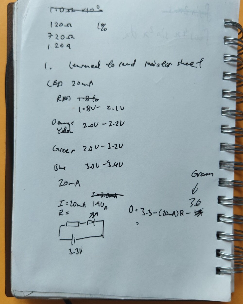
Resistor color codes and LED forward voltages
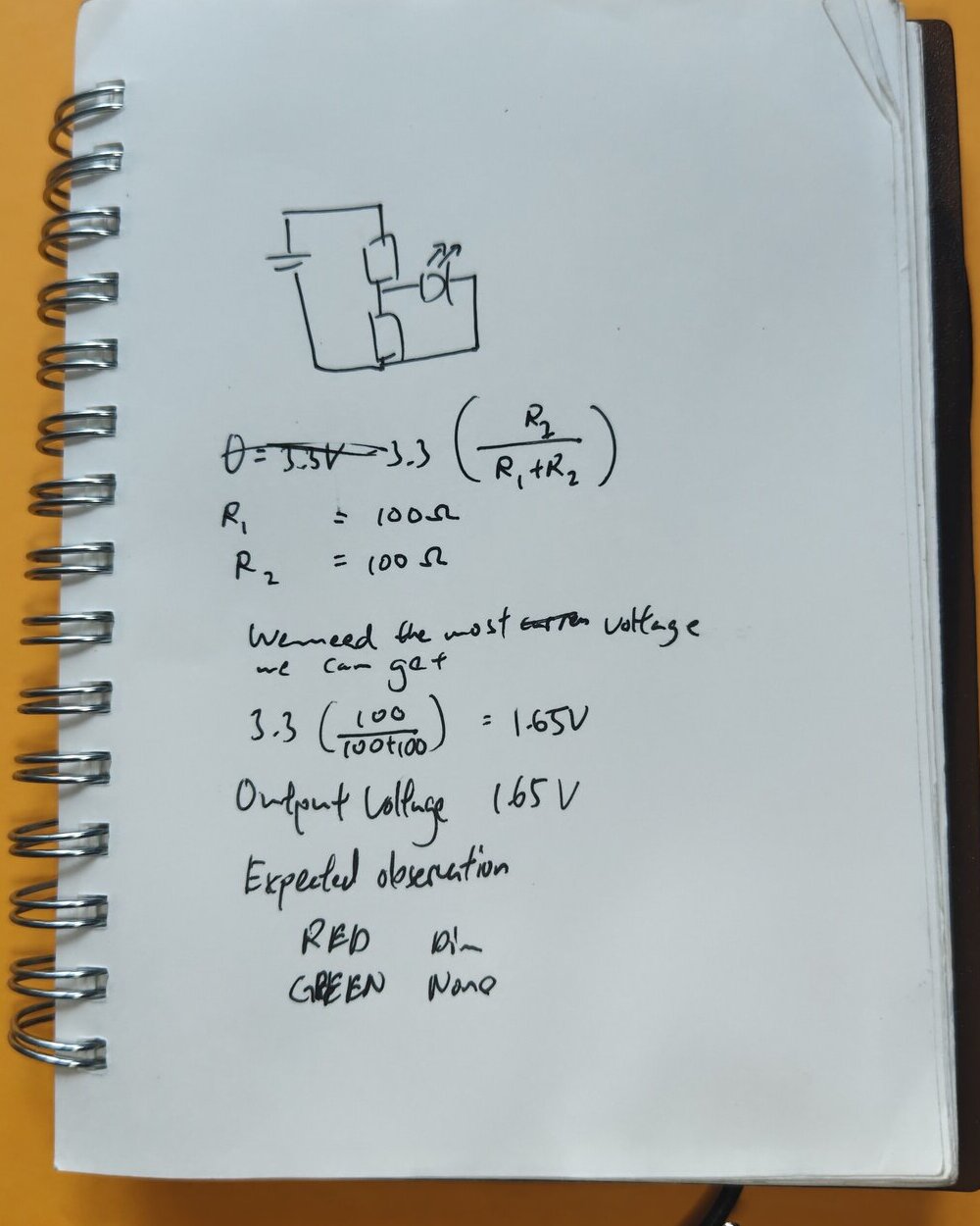
Voltage divider derivation
With 1.65V at the divider output, the red LED ($V_f \approx 2.0$V) is borderline. It should be dim. The green LED too. That's just what the formula says, I didn't know if it'd actually match.
Build
ESP32 + Breadboard
Used the ESP32's built-in 3.3V pin as the supply rail. Verified voltage with a DMM before adding any load. Every connection intentional.
Two 100Ω Resistors
Built the voltage divider. The series circuit needed a resistor way larger than what I had, so a divider let me work with what I've got. Measured 1.64V at the output, close enough to what the formula predicts.
Red + Green
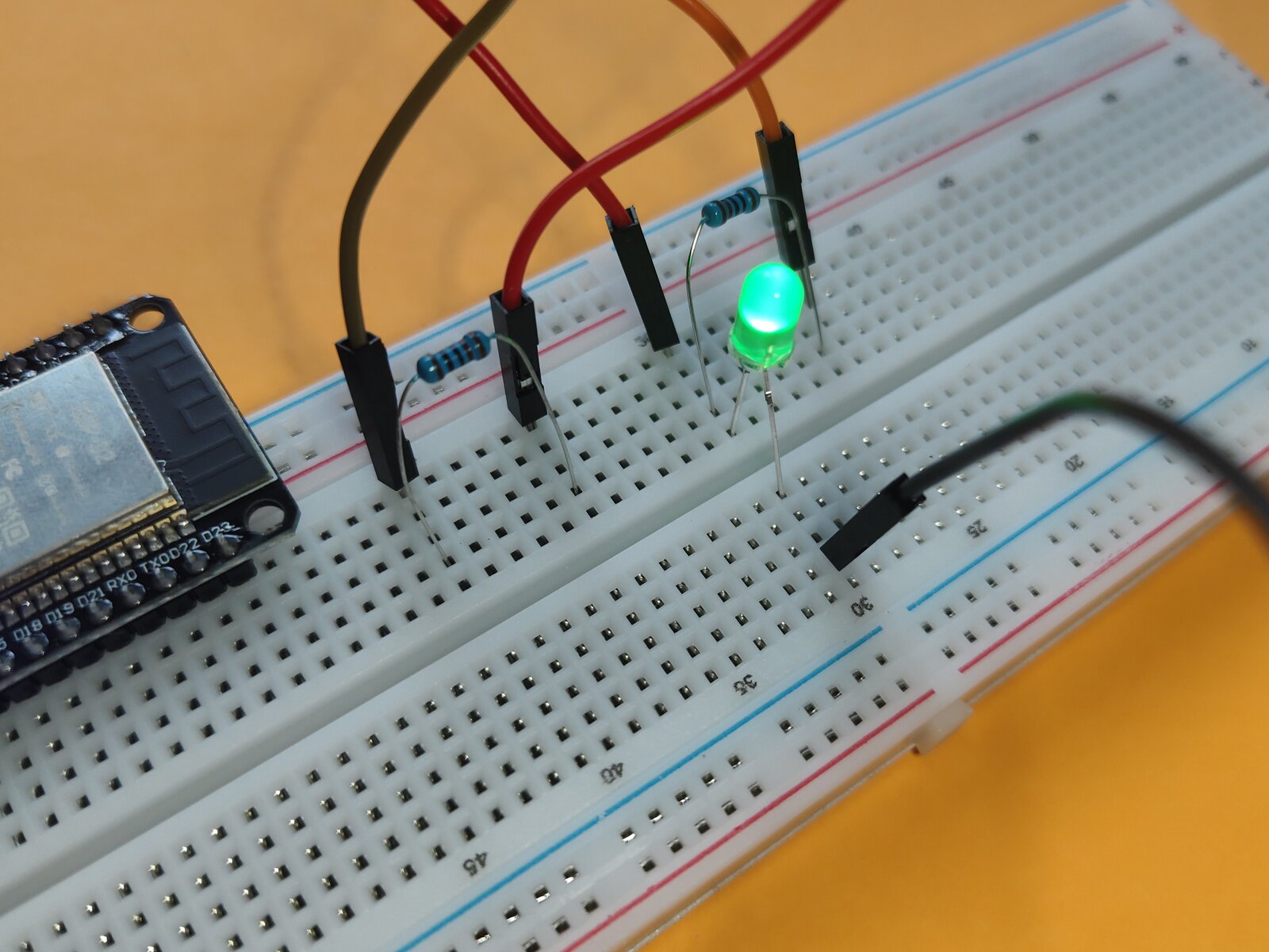
Wired each LED with its 100Ω current-limiting resistor. Red LED to the divider output (1.65V). Green LED to the full 3.3V rail for comparison.
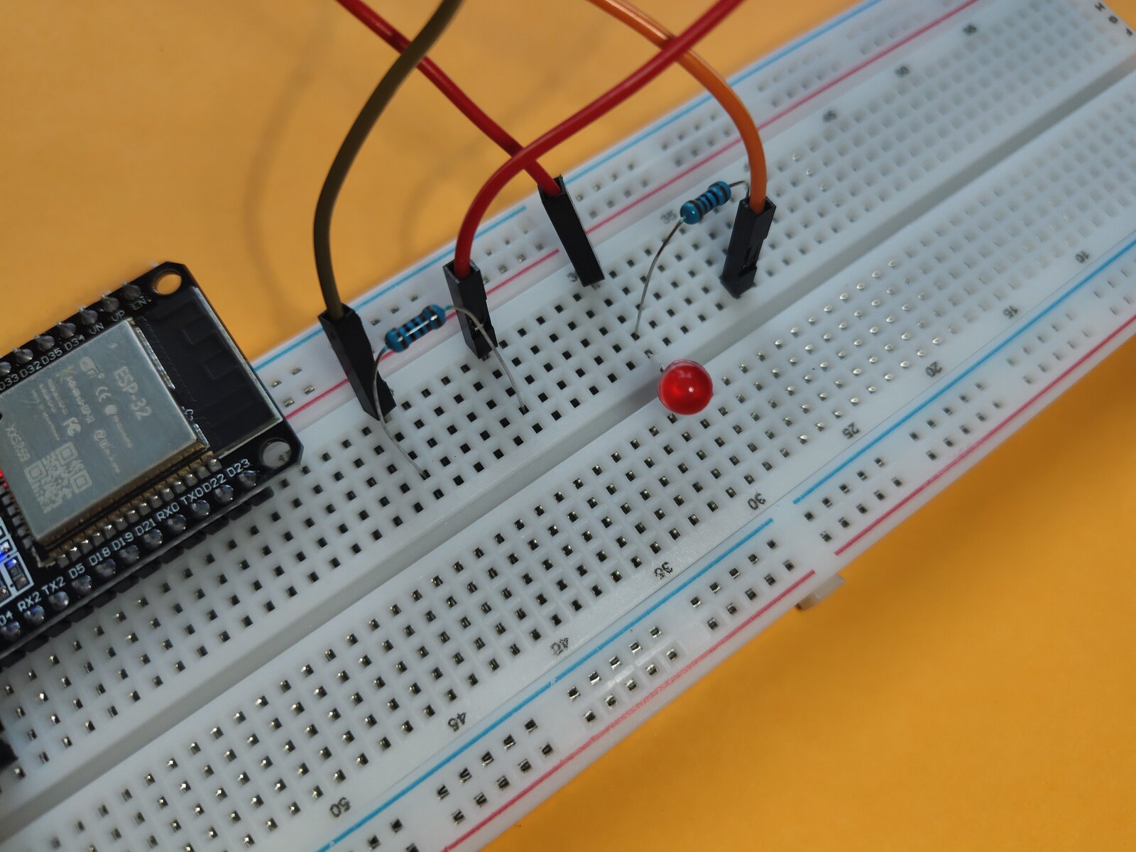
Red LED on divider output, lit but dimmer
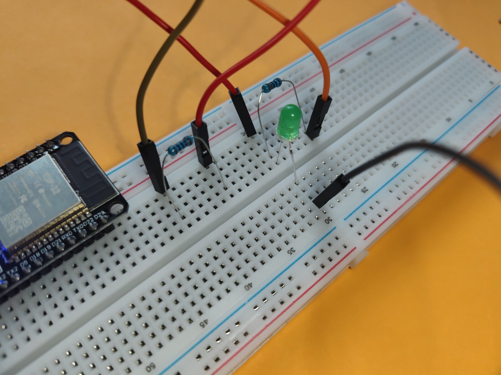
Green LED on full 3.3V rail, lit
Result
Observations
Red LED (on divider): Lit, but noticeably dimmer. The voltage divider dropped it enough that the LED wasn't fully on.
Green LED (on 3.3V rail): Lit. Not as bright as expected, but working.
Theory match: The numbers I liked happened to work. First time I made an intentional decision instead of winging it.
Final state. Both LEDs lit.
What I Learned
First time I didn't guess.
Every build before this I just eyeballed it. "This resistor looks about right." This time I actually thought about what value I needed, even if I brute-forced it on a calculator instead of doing proper math. Intentional decision beats intuition every time.
Resistors don't pull current.
Obvious in theory. Different when you stare at a circuit and realize the resistor just sits there waiting for the LED to demand current. The LED sets the current. The resistor just limits it.
Color codes are useful.
100Ω is brown-black-brown. 1kΩ is brown-black-red. Once you read a few, it becomes faster than reaching for a multimeter.